Content brought to you by PTEN. To subscribe, click here.
In the first part of this article, we discussed some of the types of computer vision (CV) sensors used in modern cars. These included cameras, time-of-flight cameras, and stereo cameras. In this second and final part of the article, we will take a closer look at thermal imaging, ultrasonics, and radar.
Looking at the New Car Assessment Programs (NCAP) for both the U.S. and regions of Europe is a good indicator of where the market is heading regarding vehicle safety systems. The sensors that we will likely see more of are thermal/infrared-based cameras.
The standards that drove the capabilities of today’s vehicles fall short in demanding performance requirements around protecting vulnerable road users (VRUs) at night where an overwhelming majority of the vehicle to VRU injuries and deaths occur. The reason is primarily driven by the current state of the market’s technological capabilities. However, regulators are moving the industry toward creating incentives to bring low-light VRU protections to market. There is no doubt in my mind that we will continue to see a rise in onboard perception systems with tremendous capabilities. And because of this, we as service professionals need to maintain high-level situational awareness of these technologies and how service operations should be properly performed on tomorrow’s vehicles.
Both the U.S. and European NCAPs vary in requirements. In both markets, those requirements are about to change. For example, in the U.S., within the 2021 Infrastructure Investments and Jobs Act bill, NHTSA has established a 10-year roadmap with a deeper focus on enhanced Pedestrian Automated Emergency Braking (PAEB) technologies, especially during low light conditions. In Europe, their NCAP does not currently test active safety systems with an environmental lighting condition below 5 lux. Twilight is >3 lux and this occurs when the sun is six percent below the horizon. For reference, streetlights bring the lux level to around 15.
Following the tragic death in Arizona of a VRU by an Uber-owned and operated autonomous vehicle back in 2018, Teledyne FLIR later presented at the Computer Electronics Show in Las Vegas how their infrared sensing technology is superior to lidar, radar, and camera vision in situations like this. Their demonstration and claim stated that the VRU was able to be detected up to three times earlier than the current suite of technology deployed on the vehicle by adding infrared thermal camera capabilities. When I saw this presentation, I was amazed by the data and performance of their system, and I certainly expected to see a significant shift in the adoption of such technologies into the market. Although this hasn’t happened yet by a great margin, I expect to see wide use of these systems in the future.
Passive vs. active infrared
Passive infrared cameras use the heat (thermal radiation) emanating from a source like humans and animals. An active system casts an infrared signal from the imaging device onto the scene so its sensors can gather low-light information.
Vehicle history: Night vision
In 2000, General Motors offered Night Vision as an option on the 2000 Cadillac DeVille by implementing the use of a passive infrared sensor mounted behind the grill which used the heads-up display (HUD) cast onto the windshield. In 2004, GM eliminated this offering. In 2002, Toyota offered Night View on the Land Cruiser and the Lexus LX470 utilizing an active system that displayed the environment in front of the vehicle to the driver via the HUD on the windshield. Audi introduced the Night Vision Assistant (passive) in 2010 on the A8 which displays images in the central instrument cluster between the main gauges. Today, Audi offers this on several vehicles (Figure 1). Audi claims that their Night Vision can look ahead up to about 1,000' and detect VRUs at just over 300'. By my calculations, a vehicle traveling at 85 MPH would have about a 3-second lead time in total darkness to take corrective action on a potential threat.

SEDAR – Spectrum Enhanced Detection and Ranging
The company Trieye has introduced a new mix of potential low-light vision solutions through the implementation of a CMOS-based high-definition short-range infrared (SWIR) sensor that allows for 3-D mapping of the road ahead in all visibility conditions (Figure 2). According to their website trieye.tech/sedar, they claim at mass production, one can realize a ten times cost reduction compared to existing lidar solutions available today.

Ultrasonic sensors

Ultrasonic sensors (Figure 3) operate based on the principles of sound waves and their interactions with objects in the environment within their vicinity. It uses the time-of-flight method to measure the distance between the sensor and the target object(s).
Primarily, the ultrasonic sensor consists of a piezoelectric transducer. This device can convert electrical energy into mechanical vibrations, therefore, creating sound waves. When an electric signal is applied to the piezo transducer, it vibrates at a high frequency, typically above 20,000 hertz which happens to be classified as the “ultrasonic” range.
The emitted sound waves travel through the air until they encounter an object in their path. When the sound waves hit the object's surface, they reflect or echo. Some of the sound waves bounce back towards the sensor where is it captured.
Signal reception is captured by the receiver, which is another piezoelectric transducer. This receiver is designed to detect the echoes of the sound waves that have bounced back from the object. Then the receiver transducer converts the received sound waves into electrical signals. The sensor's electronic circuits use time-of-flight to calculate distance. This time interval is often noticeably short, measured in microseconds.
Ultrasonic sensor diagnostics
Since multiple sensors are installed on the vehicle and their location needs to be known by the domain controller, proper sensor setup needs to be performed whenever replacement or service is required. In most cases, the scan tool and service information can guide you toward an accurate diagnosis. However, there may be other ways to assess some of the operational characteristics. Since the sensors need power to operate, they will indeed generate heat. One test I have performed in the past is by using a thermal camera (Figure 4).

Say that you had a DTC related to a particular sensor and you wanted to investigate further. One way would be to activate the sensors and look with a thermal camera. If the faulty sensor demonstrated a similar heat signature as the others that were operating normally, then one could assume that the sensor was receiving power and ground and therefore could proceed to focus on the signal circuit.
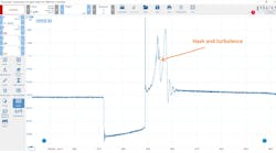
Another test that can be performed is to simply use a listening device such as a stethoscope with only a hose attached to listen to the chirps. Another could be to use a lab scope and an inexpensive microphone probe to have a look as shown in Figure 5 where I’m using the u-Scope and a parking sensor detector probe (microphone) to see the signal.

Radar sensors
An automotive forward-facing radar sensor is designed to detect and track objects in front of a vehicle, providing crucial information for various advanced driver assistance systems (ADAS) and autonomous driving features.
Essentially, the radar sensor emits a high-frequency radio wave, typically in the microwave range which resides between the frequencies of 300 MHz to 300 GHz. Most forward-facing radar sensors operate between 77 and 81 GHz which is 77 to 81 billion times a second. The primary use for this range is because of the environment this sensor is operating in. Radar sensors typically have fewer transmitting antennas than receivers (Figure 6).

Antennas are arranged in an array with known distances from each other. This is part of the mathematical equations scientists have been able to exploit to gather information about the environment around the vehicle. Simply put, the flat board radar antennas are mounted to emit radiation chirps in a cone-like fashion and the receiving antennas pick up the reflected chirps. The system calculates the distance via time-of-flight the same way cameras do. As far as the azimuth location, the sensor performs quite a bit of work to accomplish this.
Beam Steering

The continuous wave chirp transmitted from the antenna can be transmitted in unison with two or more antennas that are either closer together to each other or not. Additionally, the other antennas transmit the same wavelength out of phase which essentially allows for what is commonly called beam steering.
Check out this link (youtu.be/9WxWun0E-PM) to a MATLAB video covering this topic in more detail if you'd like to learn more (Figure 7).
Radar wave interaction: When the emitted radar wave encounters an object, such as another vehicle or an obstacle, a portion of the wave is reflected toward the radar sensor. Radar sensors can track multiple objects simultaneously.
Data fusion: In many automotive systems, the radar sensor's information is combined with data from other sensors, such as cameras or lidar, to provide a more comprehensive understanding of the environment. In the past, I have heard that the forward-facing camera is only used for watching the lane markings, and the radar was used to track objects, which isn’t really what’s happening. The system's engineer can leverage all inputs to gather intelligence about the environment around the vehicle to support vehicle corrective actions.
By continuously monitoring the environment around the vehicle, an automotive forward-facing radar sensor enhances the vehicle's perception capabilities and contributes to safer and more efficient driving experiences.
In 2021, Tesla announced that they were no longer installing radar sensors on their vehicles. Here’s a quote from their website:
“Safety is at the core of our design and engineering decisions. In 2021, we began our transition to Tesla Vision by removing radar from Model 3 and Model Y, followed by Model S and Model X in 2022. Today, in most regions around the globe, these vehicles now rely on Tesla Vision, our camera-based autopilot system.”
However, as of the first of the year in 2023, Tesla began installing their new Hardware 4 packages on the Model S and X vehicles which includes a new high-definition radar sensor. I received wind of this in 2022 and when the FCC ID became available (2AEIM-1541584), I shot on over to the FCC to have a look at the internals and this is what I found:

From what I understand, the Tesla vehicles built with radar sensors prior to the move to Tesla Vision no longer use those sensors as part of their perception systems. Looking at the vehicle configuration options, it appears that if you had one of these vehicles needing a new sensor due to sensor failure or collision, I would assume that the sensor could be decommissioned from the vehicle using Toolbox and the vehicle configuration editor. In our shop, we service several Tesla vehicles, and I have seen Model 3’s that are not equipped with a radar sensor however, the wiring harness is in place. Additionally, Tesla has also removed the ultrasonic sensors from their vehicles. I recently rented a Model 3 with this setup and noticed that the parking assistance wasn’t as robust as my vehicle, which is equipped with 12 ultrasonic sensors. During one instance, I was prompted to wait for the parking system to activate (Figure 8).

Radar diagnostics
Radar sensors are delicate devices, and their mounting locations subject them to harsh environments. Typically, if the radar sensor has been in a situation or an event that would equate to dropping the component, it should be replaced. Most radar sensors I have worked with say in bold letter words, “SCRAP IF DROPPED.” A capable scan tool, DVOM, lab scope, and accurate service information should be able to help you conquer any diagnostic challenges. And here’s a tip that helped me with a recent encounter on a late-model Toyota.
If you’re looking at a Toyota with a radar sensor on a 2018 - 2023 Tacoma and have a DTC U0235 stating that the sensor will not communicate, it may have been induced by previous interactions with a scan tool. Toyota’s service information displays a “HINT” in green stating the following:
Do not exit Test Mode (Signal Check) within 5 seconds of entering Test Mode (Signal Check). If Test Mode (Signal Check) is exited within 5 seconds of entering Test Mode (Signal Check), DTC U0235 may be stored. If DTC U0235 is output after exiting Test Mode (Signal Check), enter Test Mode (Signal Check) again, wait at least 5 seconds, then recheck for DTCs.
Why this happens has to do with the system taking inventory of the ADAS-related systems when entering test mode. If you exit before the query finishes, you will end up hanging the system in a mode causing this communication problem. I’ve looked up a 2021 Toyota Highlander and it doesn’t appear that this issue is a problem on that vehicle.
Calibration
When you’re faced with sensor removal and or replacement, you may need special calibration tools and equipment to properly place the vehicle back into service. Always check the latest service information for guidance.
Conclusion
In the second part of this article, we discussed thermal vision cameras, ultrasonic sensors, and radar sensors used to support ADAS and future SAE J3016 Level 5 vehicles, as well as explaining how these sensors work and their specific use cases. We also discussed the future of ADAS sensors and how they will play a crucial role in the development of fully autonomous vehicles. Overall, this two-part article provides an overview of the several types of ADAS sensors currently in use and their importance in the development of advanced driver assistance systems and a small glimpse into what the future is likely to bring us.
Read part one of this article here.